Internship information
- Company: Texas Instruments
- Position: Validation Engineering Intern
- Internship date: May 2023 - Aug 2023
- Location: Santa Clara, CA
- Company Website: ti.com
Texas Instruments
Worked with on the automotive SerDes product line (FPD-Link) to help create automation scripts in python. Developed an automated validation system to simulate different cables and parameters. Created correlations to help map different cable types and parameters of one cable to another cable to reduce the number of cables needed to be tested. The automated system helped to reduce cable testing times by over 50%.
FPD-Link
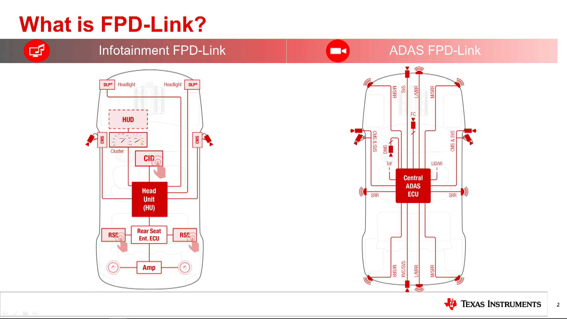
FPD-Link is a high-speed digital interface for video data transmission and is used in automotive infotainment and ADAS applications. It is a low-cost, low-power, and low EMI technology that is easy to implement. FPD-Link is a point-to-point technology that can support both uni-directional and bidirectional data transmission. It is a robust technology that can support long distance transmission over a single twisted pair cable. FPD-Link is a scalable technology that can support different resolutions and frame rates by changing the serializer and deserializer configurations.
Role
As a member of the validation team I worked on validation of features of the FPD-Link. My role in particular entailed working with the validation team to develop test plans and create an automated testing system to test a variety of different features. As a validation engineer we are considered the first client which entails what we work with doesn't always work, and we must test it similar to how our customers will.
Project
My project involved creating an automated system to validate cable parameters. The system utilizing an ISI box to replicate the insertion loss of a cable. With newer technologies coming to play the role of return loss is playing a larger role in the overall system. Therefore, my task was to emulate a variety different insertion loss values while holding return loss at a constant value to ensure the system is not affected by the return loss parameter.
Process
The following process was utilized to validate the setup. First, a plan was outlined highlighting the main hypothesis that an ISI box can be used to simulate the insertion loss for a cable while utilizing different cable to vary the return loss. Next, a test plan was created to first gather the s-params(insertion and return loss) for different STP and coaxial cable lengths. Once the s-params were calculated, the ISI box was automated and used to create a relation between the real loss and ISI box. After the correlation is created it is validated through a variety of tests ensuring link integrity.
The following is a video explaining the product line I worked for at Texas Instruments.


